
Definition: Power Attenuator
An infinitely variable power absorbing device
that allows your amp to breathe and your guitar to sustain. The ultimate volume control.
The Jim Kelley Power
Attenuator is designed to allow you to control the volume of your
amplifier by adjusting the amount of power delivered to the speaker. This allows you to turn your amp up so it can
achieve its best tone, while the Power Attenuator maintains precise control of your volume.
The L-Pad Attenuator
The Jim Kelley Power
Attenuator utilizes a time-proven engineering standard L-Pad design. An L-Pad is an
infinitely variable power divider that, when combined with a speaker, maintains constant load impedance over its range of
adjustment. L-Pads have been used to
adjust the volume of high fidelity music systems with complete
transparency for more than 50 years. At
the heart of our device is a pair of 100 watt rheostats wired in an ‘L’
arrangement. A rheostat is a large, power dissipating, wirewound potentiometer. Increasing
the amount of attenuation moves the rheostats in unison such that
as the impedance of the series rheostat increases, the impedance of the shunt
rheostat decreases. As attenuation is increased,
more power is diverted to the rheostats and less is conveyed to the
speaker. Maintaining constant load
impedance at all attenuation settings allows the natural tone of your
amplifier to come through at virtually any power level. This is a rugged, good looking,
high power device with 30 years of performance tested experience on stages around the world.
Resistance vs.
Reactance
There are two perspectives
from which to view impedance: from the perspective of the amplifier, and from the
perspective of the speaker. Generally,
the perspective of the amplifier is taken, and it is argued that in order to best
preserve the integrity of the signal, the attenuator
should present a reactive load to the amplifier. This has the effect of shaping
the frequency response. However, from the perspective
of the speaker, the way it responds to a given signal is primarily a function of
its own frequency-dependent impedance characteristics. With a reactive attenuator, the frequency
response is a combination of both the response of the speaker and the response of
the attenuator. The logic for using
purely resistive elements in the attenuator is that they are neutral with
regard to frequency, and can thus provide optimal signal transparency. Although there are other effective means for
accurately attenuating a signal, and some may be well suited in a bedroom environment,
players have found that ours is simple, practical, reliable, and great sounding on stage,
and in the studio.
The
‘Loudness Effect’
Ever notice what happens when
you listen to music at low volume? The high-end and low-end become less
prominent. Stereo systems have a
Loudness switch to compensate for this, and now due to popular demand the Jim
Kelley Power Attenuator also has 3 levels of Treble Boost compensation: 0 dB, +3dB, or +6dB. The exact amount of compensation varies as
needed with the amount of attenuation. Webster's dictionary defines dynamic range
as the ratio of the strongest to the weakest sound intensity
reproduced by an audio system. Turning down the volume on your stereo reduces
the dynamic range of the sound by reducing the strongest sound intensity.
This is what a power attenuator does - the advantage being that it allows you to
utilize your amplifier to its full capacity.
The Footswitch
True bypass footswitching
allows you to restore full power in an instant.
The attenuator footswitch also provides an auxiliary jack which,
depending on your amp, can be used to simultaneously boost gain, or select
channels whenever you switch. With the
Jim Kelley Power Attenuator you can adjust for both a clean sound, and an overdriven
output sound - both at the same volume.
An internal selector switch allows you to optimize the auxiliary switching for
your particular amplifier.
UPDATE: Demo Sound Files!!! - I talked a friend of mine, Jake, into working with me
at his home studio. We set up his Marshall head and an attenuator in the control room with us, and we
miked a 2x12 open back Marshal cabinet out in the studio. In the first sound file, I adjust the attenuator from all the
way up, to all the way down, and back again - while narrating.
'63 Strat, 50 Watt Marshall, Attenuator Zero to 10 (Listen)
In this second sound file we keep the recorded levels constant at different attenuators settings,
making for a simpler tone comparison. We recorded the same Marshall/'63 Strat setup as before, first with the attenuator at full; then at '7', '5', and '3'.
Only the Power Attenuator setting and the mic gain were changed so that we could maintain a constant level on the track.
The equalization and dynamics were not altered so you can compare the recorded sound at different levels of attenuation. The results are impressive.
Special thanks to Jake Hill.
Attenuator at 10, 7, 5, and 3 (Listen)
Jim Kelley Amplifiers TM Power Attenuator
ü
Genuine Ohmite rheostats, Switchcraft connectors,
ü
Original clarity and purity of tone - with Loudness
Compensation
ü
16 Gauge steel chassis with front panel guard
ü
New amplifier footswitch interface jack for Channel
Switching or Gain Boost
Maximum Power Input: 100 Watts
Treble Boost (Loudness Compensation)
+6dB @ 10 KHz,@ 8.25 dB attenuation
+3dB @ 10 KHz @ 8.25 dB attenuation
Line Out
Source Impedance: ~200 ohms
Voltage Attenuation Ratio: ~10:1
True Bypass Footswitch
Attenuator must be used with
either a footswitch or 4-pin mating plug
Auxiliary 1/4”
Footswitch Jack: Operates in
concert with attenuator bypass footswitch. Use this jack to control amplifier
gain boost or channel switching. Internally switchable as normally open or
normally closed. Optional LED indicator
available for additional charge.
INSTRUCTIONS
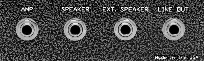
Use a short ¼” speaker patch
cord (not coaxial) to connect the speaker jack on the amplifier with the ‘Amp’
connector on the back of the attenuator.
Connect the cable from the speaker or speaker cabinet to the ¼” jack
marked ‘Speaker’ on the back of the attenuator.
Connect the 4-pin footswitch cable to the XLR jack on the front panel of
the attenuator. Do not use the amplifier
without all of these cables connected to the attenuator. If you’re using the auxiliary switching jack,
and the amp is attenuated in the opposite mode, remove the
bottom of the footswitch and slide the selector switch to its other position.
Shipping Weight: 8 lbs
Dimensions: 6” wide, 4” high, 7” deep